Mechanical Properties
This is a class related to the robot’s mechanical characteristics. The robot can be defined and used with these parameters. Reference the variables of the RobotParam class.
The parameters that make up the robot are as follows:
Robot ID |
|
|---|---|
Variable |
|
Type |
|
Maximum |
|
Minimum |
|
Default |
|
Unique ID of the robot
Robot Name |
|
|---|---|
Variable |
|
Type |
|
User-defined name of the robot
Robot Type |
|
|---|---|
Variable |
|
Type |
|
Default |
|
Indicates the type of robot, such as 6-axis vertical articulated, SCARA, x-y-z stage, delta robot, UserDefined robot, etc. -1 represents InvalidModel.
Please refer to Robot Types for information about different types of robots.
Number of Axes |
|
|---|---|
Variable |
|
Type |
|
Maximum |
|
Minimum |
|
Default |
|
The number of axes that the robot has.
Base Joint Coordinate System |
|
|---|---|
Variable |
|
Type |
|
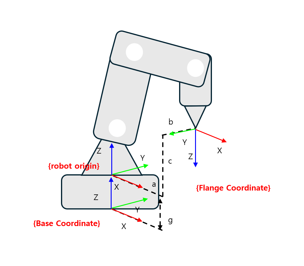
Represents the robot’s base joint coordinate system.
The value of the first drive joint (jointOrigin 0) is the relative position and orientation from the base joint coordinate system.
In the figure below, the x,y,z,u,v,w values of baseJointCoordinate are as follows:
x,y,z = 0, 0, g , u,v,w = 0, 0, 0
 baseJointCoordinate
Base Link Information |
|
|---|---|
Variable |
|
Type |
|
This is the base link information.
For detailed information about links, please refer to Link Information.
Joint Information |
|
|---|---|
Variable |
|
Type |
|
Contains information about the mechanical characteristics of the robot’s joints.
For detailed information about joints, please refer to Joint Information.
Link Information |
|
|---|---|
Variable |
|
Type |
|
Contains information about the mechanical characteristics of the robot’s links.
For detailed information about links, please refer to Link Information.
Flange Joint (Tool Free) Coordinate System |
|
|---|---|
Variable |
|
Type |
|
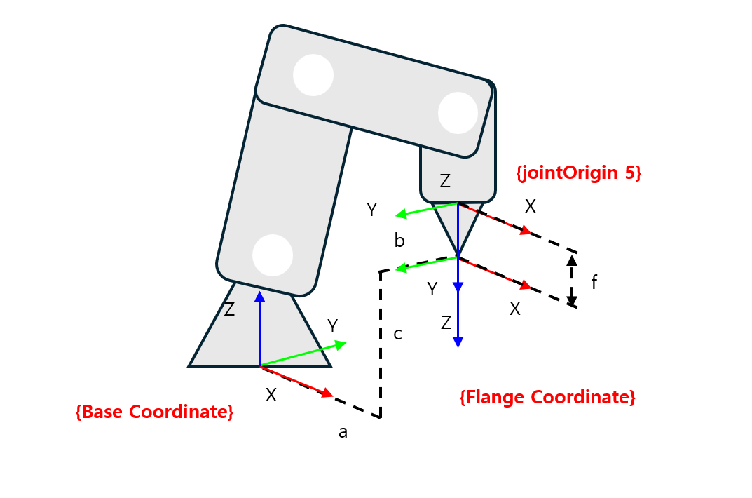
Represents the robot’s flange joint (tool free) coordinate system. Defines the end position of the robot without any work tool attached.
Represents the relative position and orientation from the last drive joint (jointOrigin) to the flange joint.
In the figure below, the x,y,z,u,v,w values of flangeJointCoordinate are as follows:
x,y,z = 0, 0, f , u,v,w = 0, 0, 0
 flangeJointCoordinate
Robot Movement Limit Range |
|
|---|---|
Variable |
|
Type |
|
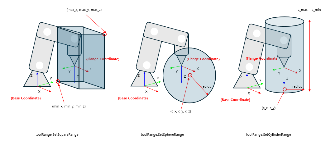
The toolRange parameter is a setting to limit the range of motion of the robot’s end effector.
If the robot’s end effector moves beyond the specified limit range, an error alarm will occur and the robot will stop immediately.
The types of areas that can be restricted are as follows:
Box
Sphere
Cylinder
 ToolRange
CP Motion Movement Limit Range |
|
|---|---|
Variable |
|
Type |
|
Restricts the range of movement possible with CP motion. The usage is the same as toolRange, only it checks the range only for CP motion.
Work Coordinate System |
|
|---|---|
Variable |
|
Type |
|
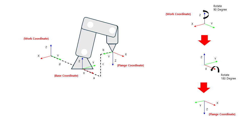
Enter the workCoordinate value to change the reference coordinate system from Base Coordinate to Work Coordinate.
In the figure below, the x, y, z, u, v, w values of workCoordinate are as follows:
x,y,z = 0, d, 0 , u,v,w = 0, 0, 90
After entering the workCoordinate value, the robot’s position values are as follows:
x,y,z = -b, d+a, c , u,v,w = 180, 0, 90
 Work Coordinate
Tool Coordinate System |
|
|---|---|
Variable |
|
Type |
|
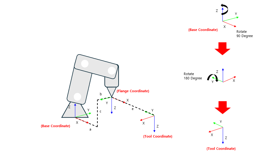
You can change the desired control point by applying the toolCoordinate value in the Flange Coordinate (tool free).
In the figure below, the x, y, z, u, v, w values of the Flange Coordinate are as follows:
x,y,z = e, 0, 0
u,v,w = 0, 0, 90
After entering the toolCoordinate value, the robot’s position values are as follows:
x,y,z = a+e, b, c
u,v,w = 0, 180, 90
 Tool Coordinate
Tool Link Information |
|
|---|---|
Variable |
|
Type |
|
This is the robot’s tool link information.
For a detailed explanation of the link, please refer to Link Information.